Transduction and quantum frequency conversion
A quantum network has to deliver photons over deployed fibre, and deployed fibre has its loss minimum in the telecom C-band around 1550 nm. Most quantum platforms do not naturally emit there: superconducting qubits live at 4–8 GHz microwaves, neutral-atom and ion platforms emit in the visible or UV, and most solid-state colour centres sit in the near-infrared. Bridging those frequencies to the C-band while preserving the photon's quantum state is the device-level problem Ezratty 2025 .
Two regimes share the name "transduction" but have very different difficulty curves. Quantum frequency conversion (QFC) shifts visible or near-IR photons to the telecom band using χ²/χ³ nonlinear optics — the same PPLN-and-pump toolkit classical telecom uses for wavelength conversion, operated at single-photon level. Lab efficiencies are 30–80 % with low added noise; this is mostly an engineering problem. Microwave-to-optical (M-O) transduction has to span ~4.6 orders of magnitude between a 4–8 GHz superconducting qubit and a 1550 nm optical mode, and there is no single nonlinear material that does it directly. Hybrid mechanisms — optomechanical, electro-optic, magnonic, and atomic-ensemble — bridge the two regimes via an intermediate excitation, and quantum-noise-limited end-to-end efficiencies are still well under 1 % Lauk et al. 2020 .
The two regimes correspond to the two arrows on the spectrum chart: a short, well-understood arrow from the visible band to the C-band, and a long, partially-built arrow from microwaves to the C-band. Until that second arrow lands, every microwave quantum computer is stuck in its dilution refrigerator.
Two interconnects (QuICs), not a pipeline
A useful corrective before going further: QFC and microwave-to-optical transduction are not mandatory stages every quantum network must contain. They are bridges between mismatched layers — they appear precisely and only where two adjacent things in the chain don't natively speak the same physical language. If every link in the chain is matched, neither is needed.
Awschalom et al. (PRX Quantum 2021) call the technology that bridges quantum systems a quantum interconnect (QuIC), and list its components: a communication channel, a quantum memory with its associated interface to the channel, a quantum transducer for connecting qubits of different kinds or different energies, encoding converters, and entanglement sources Awschalom et al. 2021 . A repeater node uses two of these QuIC pieces in series, at two structurally different places:
The same-modality case is free
If the computer at A is a trapped-ion machine and the repeater node at A also uses trapped ions, the network qubit and the computational qubit are both ions in the same trap or in neighbouring traps. The compute–network interconnect is just an ordinary local two-qubit gate, or an ion-shuttle — operations the platform already does. No transducer, no QFC inside the box. The Oxford 2025 distributed-gate experiment was exactly this shape: each module carried a 88Sr⁺ "network ion" coupled to a 43Ca⁺ "circuit ion" by a local two-qubit gate, and the photon path between modules carried the only optical step in the protocol Main et al. 2025 .
This is the clean case, and it is the reason the localisation-first pattern in the rest of the series holds together. Building the repeater nodes out of the same modality as the computers they serve makes the compute–network interconnect disappear — no patch needed, just a native operation.
The cross-modality case is where M-O transduction lives
Now suppose the computer at A is a superconducting transmon at 5 GHz, but the repeater memory at A is an SiV centre with optical access at 737 nm. The transmon has no optical transition at all; the SiV has no microwave one. To move a qubit from the transmon into the SiV memory you have to bridge microwave to optical — and that is where the M-O transducer lives. Not at the fibre interconnect — at the internal compute–network interconnect between the computer's qubit and the repeater's memory qubit. The QFC stage on the spin-photon interconnect (737 nm → 1550 nm) is a separate problem with separate hardware.
So M-O transduction shows up in two structurally different places. First, as the way a superconducting computer reaches any photonic interconnect at all — transmons have no optical transition, full stop, so a superconducting machine that wants to network must transduce somewhere. Second, as the way a repeater node of one modality couples to a computer of another modality on the compute–network interconnect. QFC, by contrast, shows up only on the spin-photon interconnect, and only when the matter qubit emits optical photons at the wrong colour.
Sometimes one device does both jobs
A subtlety the "two interconnects" picture has to flag: in many repeater designs there is no separate memory device and photon-interface device — a single SiV or NV centre carries both the comm qubit and the memory qubit (see repeaters § node architecture for the comm/memory split). The spin-photon and compute–network interconnects collapse onto the same physical defect. The only question left is whether that device matches the computer's modality — if it doesn't, transduction or QFC is the bridge, and if it does, neither is needed.
The whole pipeline in one figure
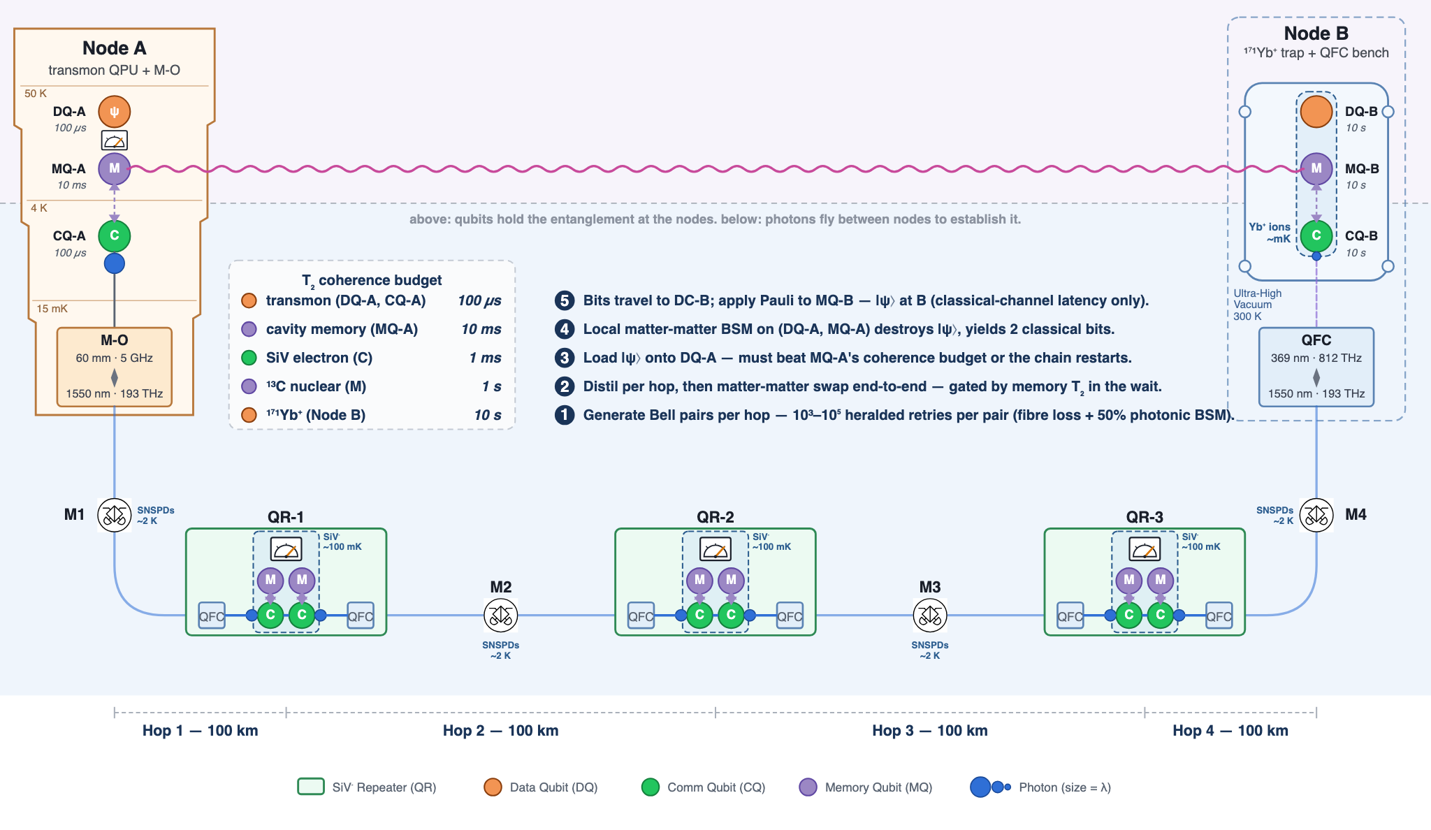
The figure depicts a hypothetical 4-hop heterogeneous link — no one has built one end-to-end yet — stretched out to make the interface chain visible from one end to the other. Reading left to right: transmon → M-O transducer → telecom fibre → [SiV-QFC → SiV repeater → SiV-QFC] × 3 → telecom fibre → Yb-QFC → trapped-ion endpoint. The QFC blocks are paired around each SiV node — one on each side, to drop 737 nm into 1550 nm for the fibre and lift it back at the next repeater. The internal architecture of each repeater is covered on repeaters § node architecture.

Where each block comes from. The chain is hypothetical, but every individual block in it follows a published system:
- Node A (transmon QPU + M-O transducer + cavity-coupled memory). Architecture: the QuIC building-block account in Awschalom et al. 2021 . State-of-the-art M-O efficiency at quantum-noise levels (~2 %): the Caltech silicon-nanomechanics transducer (Caltech) 2024 . The cavity-coupled memory transmon at MQ-A follows the Yale 3D-cavity lineage (referenced in Awschalom et al. 2021 , §3.2).
- QR-1 / QR-2 / QR-3 (SiV diamond repeater, two-emitter parallel design with ¹³C-nuclear memory). Two-emitter SiV-on-chip nanophotonic node and the 35 km Boston-metro entanglement demo: Knaut et al. 2024 . Single-emitter alternative (one comm + one memory) is the Delft NV-diamond architecture in Pompili et al. 2021 . Seconds-class ¹³C nuclear-spin memory in diamond: Bradley et al. 2019 .
- Node B (¹⁷¹Yb⁺ trapped-ion QPU + UV → telecom QFC). The reference for two QCs linked by entanglement across an optical-fibre link between trapped-ion modules is Main et al. 2025 (Oxford Ba⁺, 86 %-fidelity teleported gate; Feb 2025). UV-to-telecom QFC from an ion's native emission: Krutyanskiy et al. 2023 .
The new quantum-channel hardware is concentrated at the interface blocks — M-O at Node A, QFCs flanking every SiV repeater, QFC at Node B — plus the telecom-band fibre between them. The classical channel along the bottom carries heralds and BSM outcome bits in the usual way. The protocol splits into two phases that run independently of each other. Entanglement generation (steps 1–2) runs continuously to maintain a stock of end-to-end Bell pairs the same way a power grid maintains spinning reserve — the M-O transducer, the QFCs, the fibre, and every midpoint BSA fire throughout. Consumption (steps 3–5) draws one stored pair on demand and runs over LOCC: a local matter-matter BSM at DC-A on (DQ-A, MQ-A) using on-chip microwave gates, the two classical bits sent across the classical channel, then a local Pauli correction at DC-B. The M-O transducer is not involved in the consumption phase — it did its job earlier, helping to generate the Bell pair that is now being spent.
QFC: visible to telecom
A χ² or χ³ nonlinear crystal pumped by a strong classical laser mixes two optical frequencies into a third. With one input being a single signal photon and the other being the bright pump, sum-frequency generation (SFG) raises the signal's frequency and difference-frequency generation (DFG) lowers it. The mixing is coherent: input phase is preserved, so an arriving qubit's superposition survives to the output mode. Periodically-poled lithium niobate (PPLN) waveguides are the standard substrate; four-wave mixing in highly nonlinear fibre or χ³ photonic crystals is the χ³ alternative Ezratty 2025 .
The Knaut et al. 2024 two-node SiV-centre experiment is a useful reference for deployed numbers. It used a fibre-coupled PPLN waveguide pumped at 1623 nm to convert SiV-emission photons between 737 nm and the telecom O-band at 1350 nm, where in-fibre loss drops from 4 dB/km at 737 nm to under 0.3 dB/km at 1350 nm. DFG (737 nm + 1623 nm → 1350 nm) ran at 33 % overall efficiency at saturation; the reverse SFG path ran at 30 %. Conversion in both directions was limited by fibre-to-waveguide mode-matching rather than by the nonlinear process itself Knaut et al. 2024 .
State-of-the-art lab demonstrations have reported internal efficiencies up to 70–80 % for narrow-linewidth single-photon QFC; vendor-grade modules sold today for atomic-ensemble or colour-centre nodes typically deliver 30–50 % end-to-end including fibre coupling. Added noise is low — well under one noise photon per conversion window for properly-detuned pumps — which is what lets the same devices preserve qubit fidelity well above the 50 % classical bound. The work left is engineering: lower-loss waveguides, integrated polarisation handling, better filtering of the residual pump and Raman noise, and packaging that survives outside an optics lab Ezratty 2025 .
Microwave-to-optical transduction
A 5 GHz microwave photon and a 1550 nm optical photon differ by roughly 4.6 orders of magnitude in frequency. No single nonlinear material has a usable χ² or χ³ response that directly couples those two modes at single-photon level. Every working M-O transducer is therefore a hybrid: it introduces an intermediate degree of freedom that couples to both the microwave field and the optical field, and shuttles excitations between them. Lauk et al. 2020 surveys four mechanism families that have produced quantum-regime demonstrations Lauk et al. 2020 :
- Optomechanical / piezo-optomechanical. A high-Q mechanical resonator (a phonon mode in a suspended membrane, beam, or photonic-crystal defect) couples to a microwave LC circuit through a piezoelectric or electrostatic interaction and to an optical cavity through radiation pressure. Excitations move microwave → phonon → optical (or the reverse). Devices are typically aluminium-nitride or lithium-niobate piezo-optomechanical platforms cooled to dilution-refrigerator temperatures.
- Electro-optic (cavity-EO). A χ² electro-optic material (lithium niobate, AlN, or a thin-film integrated variant) is placed inside both a microwave resonator and an optical cavity. Pumping the optical cavity with a strong classical drive parametrically couples the microwave mode and an optical sideband, giving a beam-splitter-like Hamiltonian between the two quantum modes.
- Magnonic. A YIG (yttrium iron garnet) sphere or thin film hosts a magnon mode that couples to the microwave field via the Kittel magnetostatic mode and to the optical field via the magneto-optic (Faraday) effect. Microwave excitations are converted to magnons and then to optical sidebands.
- Atomic-ensemble / rare-earth. An ensemble of atoms or rare-earth ions in a solid host is driven so that a microwave-frequency transition (between two ground-state hyperfine levels) and an optical transition share a common excited state. A pump laser bridges the two, mapping a microwave excitation to an optical photon via a Raman-type process.
Across these families, the figures of merit are end-to-end conversion efficiency , added-noise photon number , conversion bandwidth, and operating temperature. Quantum-regime means so that the input qubit's coherence survives. As of the Lauk et al. perspective and the literature it indexes, internal beam-splitter conversions inside the device approach unity in the best experiments, but end-to-end with is still in the sub-percent to low-percent range — orders of magnitude below the QFC numbers in the previous section Lauk et al. 2020 . The Ezratty Part 4 transducer literature index (refs 707–745) tracks ongoing work, including quantum-memory-assisted on-demand transduction, multi-octave superconducting-network proposals, and SQUID-array piezoelectric couplers Ezratty 2025 .
Why M-O is the bottleneck for distributed superconducting QC
Superconducting qubits are the most-deployed platform for gate-model quantum computers — IBM, Google, Rigetti, IQM, OQC, Alibaba, and most national-lab systems are superconducting. Their qubit transition frequencies sit in the 4–8 GHz microwave band, which is why each chip lives in a dilution refrigerator at around 10–20 mK: at higher temperature the qubit's ~0.2 K thermal occupation would scramble it. The same physics that makes the qubit work makes it impossible to send a microwave photon out of the fridge through the room-temperature copper coax that delivers control pulses — single quantum-level microwave signals do not survive the warm-up Ezratty 2025 .
Three workarounds are in play, ordered by reach:
- Cold microwave links between adjacent fridges. A short superconducting coaxial line (or photonic / acoustic interconnect) held at millikelvin from end to end can carry microwave entanglement between two cryostats sitting next to each other. This is what the recent Magnard / Wallraff and Niu / Yu interconnect demonstrations rely on. It scales to a multi-fridge cluster in one room, not to a campus or metro link Ezratty 2025 .
- Microwave-to-optical transduction inside the fridge. A transducer at the cold stage converts an outgoing microwave qubit to an optical photon, which travels out of the fridge over a fibre and across arbitrary distance. This is the path that scales — but it depends on getting high enough and low enough to preserve qubit coherence end-to-end. Sub-percent means most outgoing qubits are simply lost; even with heralded protocols, the entanglement-generation rate scales as for a midpoint-source link and worse for swap chains.
- Heterogeneous transfer to a different platform. Entangle the superconducting qubit with a NV-centre or magnon spin qubit that interfaces naturally to optical photons, then network the spin. This trades the M-O transducer for a microwave-to-spin transducer plus a spin-photon interface, and is the route taken by some hybrid-architecture proposals Ezratty 2025 .
Until M-O climbs into the percent range with and a usable bandwidth, distributed superconducting quantum computing is bounded by the cold-link reach and remains a one-room phenomenon. This is why the device shows up on every quantum-internet roadmap as a critical path item, and why the Lauk et al. perspective frames transduction as the precondition for connecting microwave processors to a quantum internet Lauk et al. 2020 .
State-of-the-art performance — M-O vs QFC, side by side
Best peer-reviewed single-device numbers as of 2024–2025. Commercial / deployable values are typically 1–2× worse than the lab-best figures quoted here. The split between the two interface families is stark: QFC is mature enough that link-level demonstrations preserve qubit fidelity end-to-end; M-O is still 1–2 orders of magnitude short of fault-tolerant linking thresholds.
| Mechanism (group) | Bandwidth | Fidelity / status | ||
|---|---|---|---|---|
| Electro-optic (LN whispering-gallery; Caltech / JILA) | ~15 % bidir. | ~0.6 quanta | ~MHz | Sub-teleportation-grade. Sahu Science 370.840 (2020). |
| Piezo-optomechanical (UCSB, Stanford) | ~5 % end-to-end (47 % internal) | ~0.5–1 | ~10 MHz | Transmon entanglement demonstrated at low rate. Mirhosseini Nature 588.599 (2020); Jiang Nature 619.260 (2023). |
| Magnon-optical / Rydberg-mediated | <1 % | ~1+ | kHz–MHz | Proof-of-principle only. |
| Threshold for fault-tolerant linking | ≳ 50 % | ≪ 1 | ≳ MHz | logical. Awschalom et al. 2021 |
| System (signal → telecom) | internal | fibre-coupled | Noise | Coherence preserved? / status |
|---|---|---|---|---|
| SiV 737 nm → 1350 nm (Harvard) | ~57 % | ~30 % device; ~5 % full link | ~10 Hz dark | Yes — heralded entanglement across two-node link. Knaut et al. 2024 |
| NV 637 nm → 1588 nm (Delft / Stuttgart) | 30–40 % | ~15 % | <100 Hz | Yes — Tchebotareva PRL 123.063601 (2019); Bersin PRX Quantum 5.010303. |
| Rb 780 nm → 1522 nm (PPLN DFG, Saarbrücken) | ~70 % | ~30 % | sub-Hz | Yes — single-atom HOM preserved. Leent et al. 2022 |
| Yb⁺ 369 nm → 1311 nm (two-stage; Innsbruck / MPQ) | ~25 % / stage | ~5–10 % | ~kHz (UV harder) | Yes — Bock NatComms 9.1998 (2018); Krutyanskiy et al. 2023 |
| Threshold for repeater-useful | ≳ 50 % | ≳ 20 % | < herald rate | Yes. Azuma et al. 2023 §IV.C |
| Component | Where in 4-hop figure | Best demoed | Best demoed fidelity | Gap to “useful” |
|---|---|---|---|---|
| M-O | Node A diamond | ~15 % (with ) | Not yet entanglement-grade | Large — 1–2 orders on |
| SiV QFC | Each repeater (QR-1, QR-2, QR-3) | ~57 % internal | Entanglement preserved (Knaut) | Small — fibre coupling losses dominate |
| Yb⁺ QFC | Node B bench | ~25 % / stage | Single-photon coherence preserved | Medium — UV starting wavelength makes it harder |
Progress on the cross-modality pipeline — what has actually been built
The pipeline figure earlier on this page draws an aspirational cross-modality system, assembled from the QuIC reference architecture in Awschalom et al. (PRX Quantum 2021) Awschalom et al. 2021 . The honest position as of 2026: no single published experiment runs the whole thing — transmon compute + M-O transducer + matter memory + QFC + fibre + heralded entanglement + mirrored stack at the far end — end-to-end. The closest experiments close either some of the boxes, or all of the boxes but at lower stakes than full entanglement distribution between two computers.
The full memory + entanglement chain — Knaut et al., Nature 629, 573 (2024)
The cleanest demonstration of the memory + heralded entanglement + telecom-fibre half of the picture. Two SiV-in-diamond nodes sit in Cambridge and Boston laboratories, connected by 35 km of deployed telecom fibre at 1350 nm (PPLN QFC from the SiV's native 737 nm). Each node uses one SiV centre as both comm qubit and memory (see repeaters § node architecture). The protocol runs end-to-end: each node emits a matter-photon entangled pair, the photons fly to a midpoint photonic BSM, the herald fires, the two nodes are left with comm-A ↔ comm-B Bell-paired, and the entanglement is mapped into the nuclear-spin memory for storage. QFC ran at 33% (DFG) / 30% (SFG), the heralded entanglement fidelity stayed above the classical bound after fibre transit, and the nuclear-spin memory held the state for the herald round-trip. The catch is that the link is same-modality end-to-end, so there is no transmon and no M-O transducer in the picture — the compute–network QuIC collapses onto operations inside the SiV itself Knaut et al. 2024 .
Closing the M-O transducer box on a real transmon — Warner et al., Nature Physics 21, 831 (2025)
The first compute–network QuIC operating at single-photon level on a superconducting transmon. The Lončar group at Harvard, with Rigetti supplying the qubit, used a thin-film lithium-niobate electro-optic transducer to drive a transmon coherently with optical pulses — optically-driven Rabi oscillations on a real superconducting qubit without measurable degradation of its coherence time. Conversion efficiency up to 1.18%. Single node, no fibre between two QCs, no entanglement, but this closes the M-O-transducer box on a real transmon and shows that the compute–network QuIC is becoming experimentally viable on the superconducting platform Warner et al. 2025 .
Coherent (not yet quantum) link between two fridges — Zhou & Tang et al., Nature Photonics 20, 579 (2026)
A 1-km photonic link between two superconducting fridges, but only at coherent-classical level. Two AlN electro-optic transducers ("Felix" and "Albert") sit in two separate dilution refrigerators at Yale, each up- and down-converting between ~5 GHz microwave and 1573 nm telecom optical, joined by a 1 km fibre. Reported on-chip transduction efficiency >0.1% per node, end-to-end link transmission −60 dB. For comparison, 1 km of coaxial cable at 5 GHz would lose ~1000 dB; commercial electro-optic modulators would lose −140 dB. No memory in the picture, no entanglement: signals transferred this way are classical coherent waveforms, not heralded Bell pairs. To distribute entanglement, transducer efficiency has to climb from ~0.1% into the percent-to-tens-of-percent range with sub-photon added noise, and a memory has to be added at each node so the herald can be waited out Zhou et al. 2026 .
Encoding translation between photonic encodings
A separate flavour of conversion sits inside the optical band: translating between the photonic encodings different parts of the network use. The qubit-page encoding zoo — polarisation, time-bin, dual-rail (path), frequency-bin, Fock, coherent-state — names the choices; networking those choices means converting between them when subsystems disagree Kumar et al. 2025 .
- Polarisation ↔ time-bin. A polarising beam splitter plus a delay line maps the two polarisation modes onto two time-bin modes (or the reverse). Used when the source emits polarisation-encoded photons but the link is a deployed fibre that scrambles polarisation, in which case time-bin is the transmission encoding of choice — Caltech's 2024 time-bin teleportation at 1536.5 nm is one example of operating directly in the time-bin encoding Ezratty 2025 .
- Time-bin ↔ dual-rail (path). An unbalanced interferometer converts the two time-bin modes into the two output ports of a beam splitter, and vice versa. Used at receiver nodes where a Bell-state measurement or a cavity interaction wants spatial-mode inputs.
- Polarisation ↔ dual-rail (path). A polarising beam splitter does the conversion in one element. Used routinely inside linear-optics Bell measurement assemblies that combine photons from polarisation-encoded sources.
These translations are linear-optics operations on a single photon — they are not quantum frequency conversion and they do not span the microwave-to-optical gap. They sit alongside QFC and M-O transduction as the third axis of "make the photon match the next subsystem" the link layer has to handle.